There are so many parts and so many steps, that I'll just show some of the main assemblies as I completed them, and some of the minor changes I made.
The first step was to build the base for the trainer. The base consists of two parts - a lower box that sits on the floor, and the moveable box on top that the trainer is mounted on.
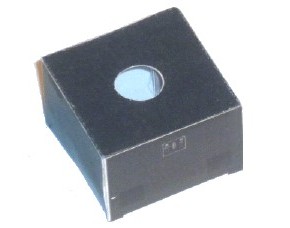
Here's the lower box with the hole for the
upper box's mounting tube . . . the box is only
about 3/4" square and a half inch high.
|
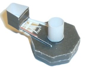
. . . and here's the upper box with the external
motor and drive belts. At just 0.8" across the
flats, and 0.3" high, it was difficult to make.
|
. . . the bottom of the upper box with the 0.25" diameter mounting tube installed . . .
|
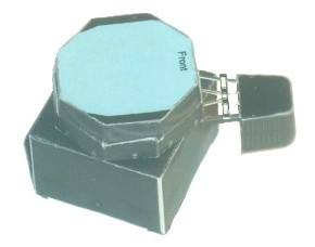
. . . and the two of them assembled . . .
|
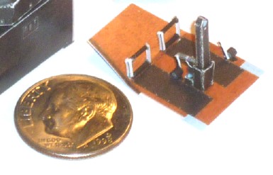
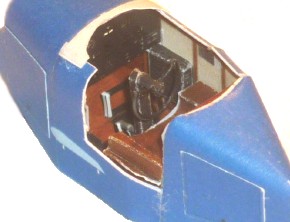
The next step was to start the trainer itself. In keeping with plastic modeling tradition, the cockpit was first up, and just to show you how small this model is, here's a picture of the cockpit floorboards with a shiny new dime.
|
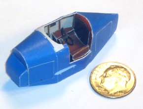
The finished fuselage with the dime . . . Cute! And SMALL!
|
The cockpit. At this size, the seat was a very difficult fold . . .
|
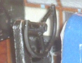 It's difficult to see in this scale, but I made the steering yoke wheel from plastic instead of using the paper version. I used plastic rod (stretched plastic sprue) bent to form the wheel, short lengths of the same for the three spokes of the wheel, and a slightly larger diameter piece of plastic rod for the steering wheel stem. It looks much better than the folded paper version (and also much better than the photo, which was taken before touch-up with a felt-pen).
|
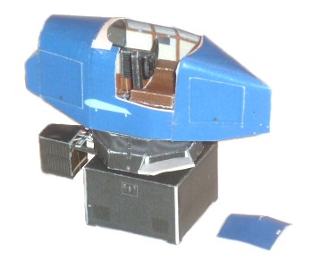
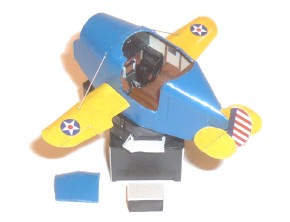
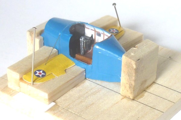
The fuselage sitting on the motorized drive and actuator boxes. Small blue object at lower right is the door to the cockpit.
Note the airfoil-shaped light blue marking on the side of the fuselage - that's where the wing root will attach.
|
When the fuselage was finished, the cut edges of many parts were white paper colored (see photo above), as opposed to the surface color. I tried to touch them up, first with a blue felt-tip pen, then with mixed paint, neither of which produced satisfactory results, so I masked off the interior of the cockpit, fixed the door in place, mixed up some paint of the appropriate color, and airbrushed the entire fuselage. This produced a uniform color, and covered the white cut edges of the paper parts. Here's the fuselage directly after spraying it blue. Note the itty-bitty little wings in the process of being folded up at the bottom of the picture. Tiny!
|
In the above picture, you can see the tiny little wings being folded up and ready for glueing. There was an interior box spar made from paper, the wing surfaces themselves, and separate ailerons which were added when the wings were dry.
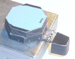
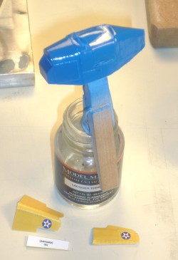
The finished wings are butt-glued to the side of the fuselage. There is a marking on the fuselage showing where to glue the wing root (you can see the light blue wingrib-shaped spot two photos up), but painting the fuselage would obscure this marking, so before I painted the fuselage, I made a fixture that aligned the wings in the correct position to be glued on. Since the wing thickness tapers from root to tip, the fixture needed to have a sloping surface for the wings to rest on. The thin white sheet plastic under the tip of the balsa sheet under the wing provided the exact slope needed for the wings to be glued on straight.
Here's a photo of the fixture used for attaching the wings.
Thin guitar wire was used for the wing bracing cable, which worked perfectly. I didn't remove the model from the fixture until I was sure both the wing/fuselage joint and the wire attach points were completely dry. Those straight pins look huge!
. . . and couple more views of the fixture . . .
|
|
|
With the wings in place, it was time for the tail surfaces.
The stabilizer as shown on the parts sheet was twelve separate pieces, which when assembled, resulted in one left, and one right stabilizer. These two halves would butt-join to the fuselage. I wanted a more robust assembly, so a full-length spar made from a piece of super-thin, but very stiff wood was incorporated, which was glued to the bottom of the stabilizer halves to make the two halves into a one-piece assembly. A slot was cut in the back of the fuselage for the stabilizer spar. At this point, the fixture for assembling the wings to the fuselage came into use again. The block that held the rear of the fuselage in place in the fixture was removed, the fuselage p[laced back in the fixture, and taped down. The stabilizer was slipped into the slot, blocked up so it was horizontal, and glued in place. After it was dry, the four wire struts seen on real Link Trainers were added, which I made from small guitar wire. There are two struts on each side that go from the bottom of the fuselage to the bottom of the stabilizer.
The rudder and fin were very straight-forward, and were simply assembled and glued in place.
|
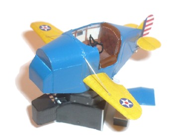
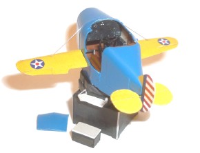
It's finally starting to look like a Link Trainer!
|
The step-stool box to help climb into the trainer has been completed. Here's a couple more views of the progress at this stage . . .
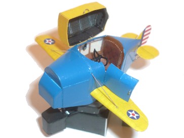
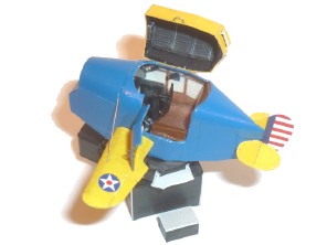
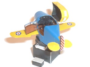
A blind/night-flying trainer isn't much good without a hood, so assembling and installing the hood was next. Here it is with the hood installed in the open position, complete with a little door handle!
The door was also added in the open position - also complete with its own tiny little door handle!
|
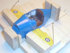
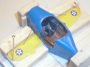
A couple more views with the blind-flying hood in place . . .
|
|
|
So . . . looks like it's done, I says to myself. And then I made the mistake of bringing it to the next model meeting, where some mischievous soul commented:
"Say - isn't there a desk and a chair that go with that thing?"
"Ummm . . . Not on the card model there isn't," I respond weakly.
And then another helpful soul added;
"Y'know, the museum has one of those over in the Personal Courage Wing (the old Champlin Fighter Aces Museum Collection)."
Oh that's just great. Not only has it been sugggested that it's not really done without the desk and chair, a kind soul has pointed out that a real life Link Trainer sits not 70 yards away that I can use for reference. After the meeting, I shamble over to the Champlin Fighter Aces Collection Personal Courage Wing, and there, in all it's glory, sits a Link Trainer.
Complete with Desk, Chair, Map Follower, and a helpful display sign which I soon discover is perfectly positioned to prevent me from getting the photos I need. It doesn't help that the lighting is actually worse than the lighting inside the Great Pyrimid on the Giza Plateau, and that the rope cordoning off this little jewel keeps me a full ten feet away from it. The flash on my little digital camera is good, but not THAT good. I endeaver to snap as many shots as I can, and resist the urge to sneak over the rope for closer shots. The pictures I do get, plus pictures scavanged off the 'net, allow me to take the next step, which was to scratch the desk, chair, and map-follower.
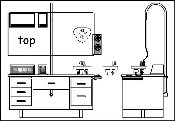
After much study, hemming, hawing, scribbling on, and taking measurements off of various photos, and actual pieces of furniture, a 1/48 scale scale drawing of the desk and it's various accessories gradually came together in Coreldraw. For the instrument boxes on the desk, I used actual photos of the instruments themselves scaled to the size of the box on the drawing. A note of caution if you decide to make a desk yourself - the drawing below is in "fit-to-article" scale, not 1/48th.
With the drawing finished, construction began. VERY small blocks of basswood were cut to size and sanded to finished size on the belt-sander (Really!) to make the two main desk drawer cabinets (0.325" x 0.425" x 0.5") and the large center drawer (0.5" x 0.49" x 0.16"). (**Note to reader: It can be highly entertaining to sand something so small on a power tool so big).
The drawer cabinets and the center drawer were glued to the bottom of a desk-top fabricated from 1/32" sheet plywood. The particular Link Trainer desk I used for reference did not have legs. It had supports made from boards - one for each drawer cabinet, going from front to back, the two of them connected by a span-wise board across the bottom of the desk. The desk had a back panel board sheet that just covered the hole in the rear of the desk.
The candy-cane-shaped support for the map-follower cables was made from very small diameter stainless tubing bent to shape. To bend the tubing without breaking or crimping it, a piece of piano wire was inserted in the tubing, the tubing was bent to shape, and the piece of piano wire removed. Voila! A nice smooth bend with no kinks! The tubing was installed via an electrical junction box on the back of the backing board made from two short pieces of plastic tubing and a small oval of sheet plastic.
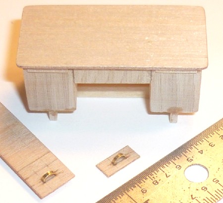
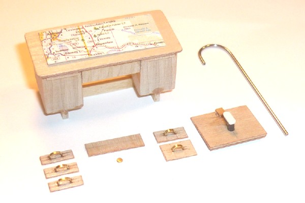
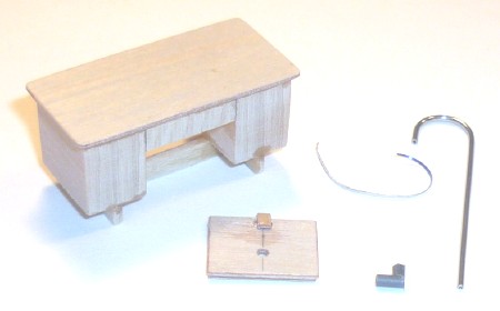 Here's the desk main assembly, the back panel, the candy-cane cable support, the little electrical junction box, and a piece of aluminum strip cut from a soda can to use as the pipe strap that holds the cable support to the back of the desk panel. To give you an idea of the comparative part sizes, the desk is 1.2 inches long.
Here's the parts dry-assembled to check for fit . . .
|
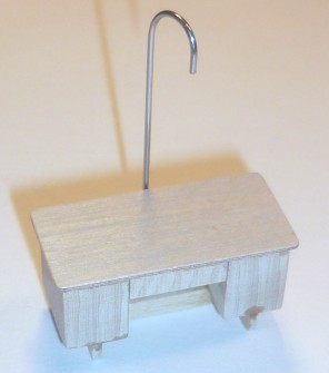
. . . the front of the desk . . .
|
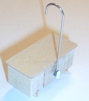
. . . and the rear . . .
|
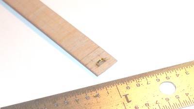 Next, the drawer fronts. A piece of 1/64 sheet ply was cut the width of the drawer fronts for the side cabinets, and the long edges sanded round. Two parallel lines were drawn so the handles would line up. Drawer handles were cut from a thin strip of brass sheet and bent into handles. The ends were inserted in short slots cut on the pencil lines. Here's the first of the six drawer fronts.
|
One drawer front done, and one being made.
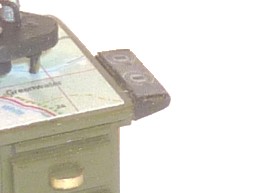
In this picture, you can see the ends of the two retractable work tables just below the lip of the desk top, one above each set of drawers. they are represented by two very narrow strips of 1/64th sheet plywood.
|
The next photo shows the main desk components finished and ready for assembly - the desk, five drawer fronts with their brass handles, the center drawer with it's round brass key lock (a tiny little 1/32 inch diameter piece of brass punched out while I was making brass washers), the back panel for the desk with the electrical junction box in place, and the candy-cane-shaped electric cable support. A preliminary map is sitting on the desk. I took a map of our local area to the local copy place and shot it down to a really tiny size and cut it out. Looks great!
|
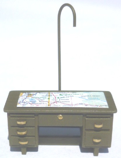 Assembled and painted.
The drawer fronts, back panel, electrical junction box, and candy-cane-cable support, along with its piping strap support were all glued in place with C/A, and the desk painted the obligatory army olive drab. When the paint was dry, a tiny paintbrush dipped in thinner was used to clean the paint off the brass drawer handles, brass key lock on the center drawer, and the metal strap holding the cable support in place on the back, and the basic desk was complete.
Love those shiny brass handles!
|
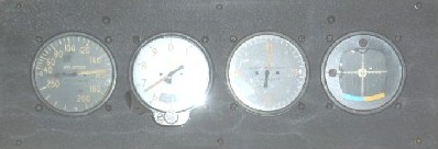
There are three instrument boxes on the desk - two on the top, and one on the right-hand end. Instrument panels for the two desk-top boxes were created using photos of the real boxes, and a graphic was used for the two dial controls on the right side box. The instruments were scaled to 1/48th scale in CorelDraw along with a re-creation of the Link Trainer instrument panel (more on that later), arranged inside the border of a four inch by six inch box, exported as a bitmap file, and converted to a jpg file. The instrument panel file was taken to the local drugstore via a handy USB drive, and printed out as a four by six inch photo, and Voila! Scale photo instrument faces!
|
The instrument faces panel for the first instrument box . . .
|
|
. . . the face panel for the second instrument box . . .
|
|
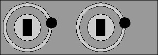
. . . and the control dials for the right-hand instrument box.
|
|
The desktop and desk-end boxes were made from small pieces of basswood sanded to shape, glued to 1/64 plywood sheet bases, and painted. The instrument faces were cut from the photo print, and glued on the front face. The right desk-end box was made the same way, painted, and the control dials cut from the photo sheet and glued to the top of the box.
/TD>
|
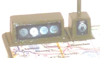
The two finished desk-top instrument boxes . . .
|
. . . and the desk-end controls box.
|
|
|
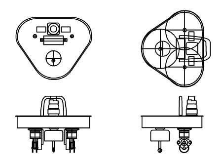 Next up was the map follower. The map follower literally follows the map, showing the operator sitting at the desk the route the pilot is taking while he "flies" the Link Trainer. It's a complex little piece of equipment that had to be done right to give a realistic impression. The first step was to make a scale drawing. Lots of eye-balling, and many measurements taken off photos later, and a fairly decent scale drawing of the map follower emerged in CorelDraw. All that remained was to convert the results into a scale version that looked the part, in spite of it's miniscule size.
|
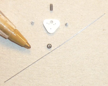 Here are some of the main components - you can see how small they are compared to the tip of a regular ball-point pen. From top to bottom, the post the cables are routed into, the main body of the follower (the white piece of plastic), the two silver-colored metal main wheels on either side of it, the forward wheel stepper post, and a piece of wire that will be used for the wheel posts and the handle on top of the map follower.
|
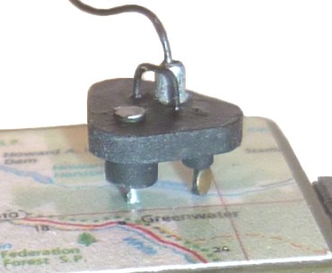
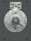
Here's the finished map follower following the pilot's course on the map. It's quite small - the main body is about one quarter inch long on a side, and in person, it looks pretty good. I've substituted brass main wheels for the silver colored ones.
The cable routed into the top of the map follower was made from a piece of thin copper wire separated from a piece of multi-strand electrical wire, painted black, and pushed into the candy-cane-shaped cable support tube at the top end.
|
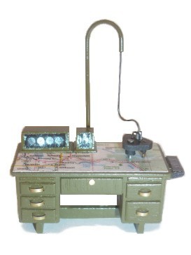
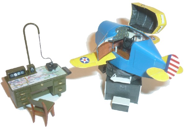
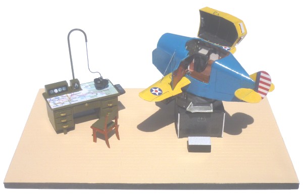
Here's the finished desk for the operator.
Cute, huh?
Now all the operator needs is a chair.
|
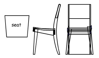
Back to measuring photos and furniture, and in short order, I've got a scale drawing of the chair . . .
|
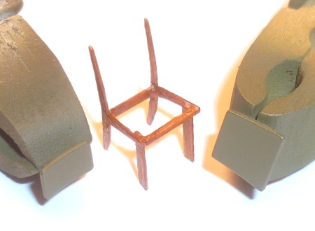
. . . followed by chair parts, here being painted. On the left, the chair back cushion, center, the chair structure made from 1/64 ply pieces glued together, painted tan, and over-coated with clear candy orange, to give that polished wood look, and on the right, the seat cushion of the chair.
|
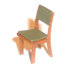
And here's the finished chair, ready for use. It's a tiny little thing, roughly about 0.66 inches tall, about 0.34 inches wide at the widest point, and about 0.35 inches deep.
Pretty neat, huh?
|
Just a few more small details, and I'd have this project ready for the "Trainers" display at the Museum of Flight. One of the things I wasn't quite satisfied with, was the instrument panel provided on the card model sheets. Small this model may be, but the instrument panel is both quite visible, and comparatively quite large, so it needed to look good. I had found a set of left and right side pictures of a complete Link Trainer instrument panel on the internet, so I used a variety of graphics programs to put them together, and cleaned them up as best I could. The result was quite satisfactory for such a small scale. Here's how it came out . . .
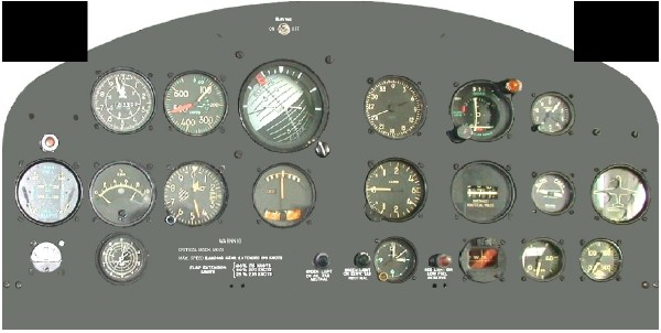
Once complete, all I had to do was print it out to the proper scale. I made a four inch by six inch rectangle in Coreldraw, measured the instrument panel in on the card model, imported my instrument panel into CorelDraw, scaled it to the dimensions I had gotten off the card model instrument panel, and moved it into the four inch by six inch box I'd made. At the same time, I imported the instrument panel faces for the two desk-top instrument boxes and the right-side-desk control box into the same 4 x 6 inch box, replicated them all a bunch of times for good measure, and ended up with this sheet of 1/48th scale instrument panels and instrument box panel faces.
NOTE: The graphic below is scaled-to-fit-article scale, NOT 1/48 scale.
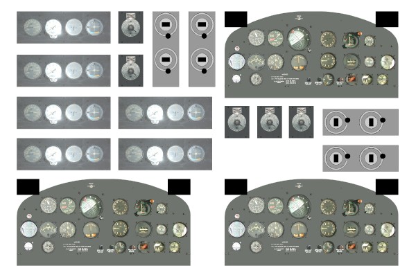
With the above graphic drawn up in CorelDraw in a 4" x 6" box, I exported it to my trusty USB drive, zipped up to the local drugstore, and printed it out as a 4" x 6" photo, and "Voila!" Instant 1/48th scale instrument panels and instrument box faces! Plus Spares! Pretty cool! Back home, I cut out an instrument panel, and glued it in place. It looks pretty good. You can just see it in this view of the Link Trainer display.
|
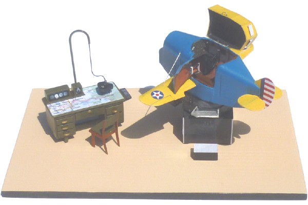
All that was left to finish the project was a base to set the pieces on. I used a 2.85" x 4.5" piece of 3/32" sheet plywood with a sheet of 0.020" sheet plastic spray-mounted to it. The sheet plastic was scored to represent a wood floor, sprayed a tan color, given a light coat of Future floor polish, and finally sanded lightly to take the gloss off. With the previously completed components placed on the wood floor base, my little Link Trainer diorama was now complete, and ready for the Trainer Display.
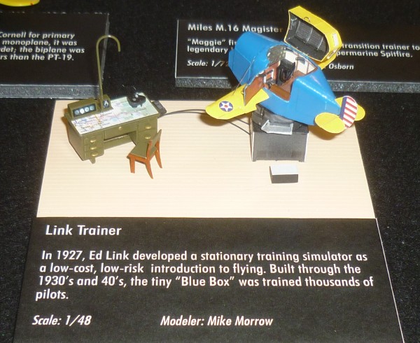
Here's one half of the Trainer Display at the Museum of Flight right after installation, and just before the cover was put on the display case. The little Link Trainer model is front and center.
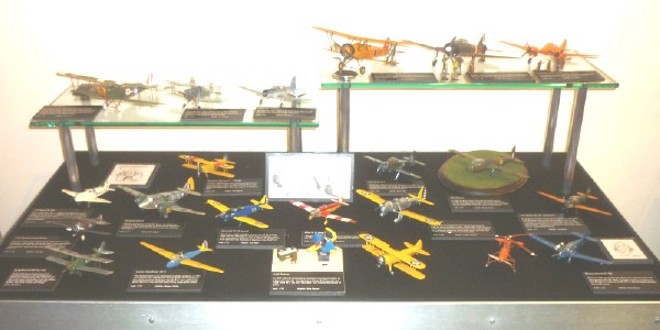
. . . and a close-up shot of the Link Trainer in the display . . .
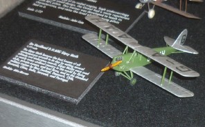
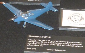
. . . along with a couple of shots of the other two models I had in the Trainer Display . . .
|
. . . a Dehavilland Tiger Moth . . .
|
. . . and a Bf-108 Taifun.
|
A final parting shot of the Link Trainer . . .
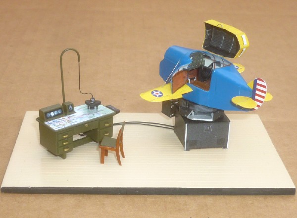
In spite of the short time frame available to finish this project, it managed to come out okay, and it was a fun build.
|
|

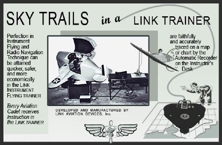 Out of disaster, sometimes comes opportunity. Forced to face up to their pilot's lack of bad weather and night-flying skills, the Army searched for a solution. Edwin Link turned his pilot trainer into an instrument trainer, and presented that solution. In 1934, Link flew to a meeting in foggy weather conditions that the Air Corps regarded as unflyable. This demonstration of instrument flying resulted in the Air Corps ordering six trainers at $3,500 each to help train pilots in the art of instrument flying at night and in bad weather. In 1935, the Japanese Imperial Navy became Link's second customer.
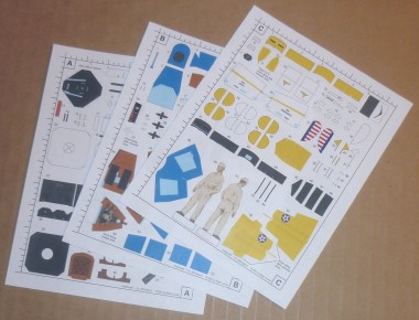 The card model was printed out on three sheets, and this is what it looked like before I started: