| Back to the Plastic Scale Modeling page |

|
|
STAR WARS B-Wing Heavy Assault Starfighter the 1/94 scale MPC snap-together kit by Michael Morrow 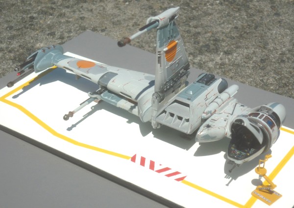
|
This model was one of two models I built for the Northwest Scale Modelers Museum of Flight science fiction themed display called "FANTASTIC VOYAGES - The Hardware of Science Fiction", which was on display from November 5th, 2009 to February 4th, 2010. The other model a model I built for the display was Thunderbird No 2. ( presented here ) from the old BBC marionette puppet show called "International Rescue". It was a great display, as there were a lot of models from other famous science fiction series and movies, and they were all well done.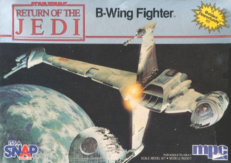 The model is the old 1/94 scale MPC snap-together kit which I have had sitting in my stash of kits almost since the movie RotJ came out, but never quite got around to building. The Museum of Flight science fiction display was the perfect excuse to drag it out and build it.
One of the big problems with spaceship models is figuring out a realistic way to display them "in flight" in space, without resorting to some kind of cheesy-looking display stand that you know isn't supposed to be there, and you don't want to see it, but there it is, big as day, distracting from the model. So, I was most pleased, while looking on the internet for B-Wing color scheme information, to come across a piece of art work showing a B-Wing Starfighter sitting on the ground. That piece of art was the inspiration for this build, and it worked out rather well. I would show you the art here, but it happens to be a copyrighted piece that was done for a STAR WARS book. If you would like to see it, you can probably find it on the internet, or you could support the artists who did the work by picking up a copy of their book. The art work showing the B-Wing fighter sitting on the ground is (supposedly) on page 138 of this book (don't take my word for it - double-check that it's the correct book before picking up a copy!):The Build The MPC 1/94 scale STAR WARS B-Wing Fighter is a snap-together kit, but I didn't let that keep me from providing my own entertainment. I could see that it was going to be difficult to add detail and paint the model in one big integrated snapped-together piece, so at various points during the assembly, major components were cut in half with a razor saw to facilitate painting and detailing. The main wing became two pieces, and the cockpit module, which would have been trapped between the two main wing halves during assembly, also became two pieces, having been cut in half between the cockpit and the aft end. All this cutting and sawing would allow me to build, paint, and detail the model as seven separate sub-assemblies, before final assembly (left main wing, right main wing, engine assembly, front cockpit pod, rear cockpit pod, folding wing cross assembly, and the double pod assembly that fits between the engine and cockpit pod). I also cut the canopy shell off the cockpit pod so it could be displayed in the open position. Sadly, I did not have a digital camera when I built this model, so I can't show you photos of the build in process, but I can show illustrations of most of the steps. |
|
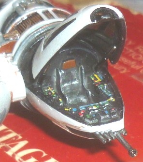
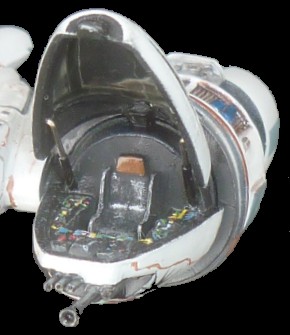
The Cockpit I had already decided to display the canopy in the open position and without the pilot. Soooo . . . . . since I wasn't going to use the pilot blob, I needed something that actually . . . well . . . looked like a seat as opposed to the stack of rectangles in the kit cockpit tub. |
 . . seat side is red outline |
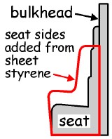
 . . . and here's the finished seat. |
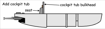 The kit seat is integral with the rear cockpit bulkhead, so the simplest and cheapest way to do this was to put sides on the seat like real seats have, to keep the pilot from sliding around. A pair of seat sides were cut from styrene sheet plastic and glued to the sides of the seat. This very simple and cheap modification improved the seat's looks immensely. I sprayed the tub flat black, picked out all the buttons and knobs in various colors, and then dry-brushed the seat and all the boxes silver to both highlight their outlines and to show wear and tear. The cockpit tub was then glued into the bottom half of the cockpit pod.
 |
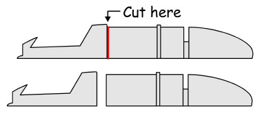 Displaying the canopy in the open position, ala the piece of art referenced above, meant opening the canopy, so the first step was to cut the canopy away from the top of the cockpit pod as shown here. Make the cut directly behind the lip of the canopy section (where the red line is) so that it results in a smooth rear face to the canopy frame section.
 |
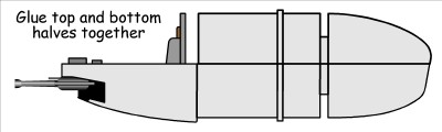
. . . . now the top and bottom halves of the cockpit pod get glued together . . . |
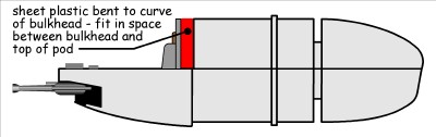 You'll probably need to fill a small space between the cockpit tub bulkhead and the top half of the pod. I cut a strip of plastic the width of the space, curved it to match the top of the bulkhead, and glued it in place between the bulkhead and the top of the pod. It should be a straight line between the top of the bulkhead and the top of the pod. Fill and sand the seams around the plastic strip to make it smooth.
 |
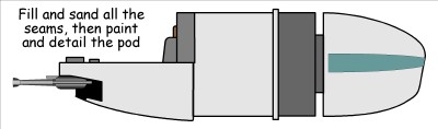
After filling and sanding all the seams on the pod, it can be painted and detailed. |
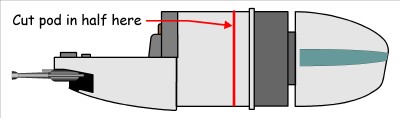 When the kit is assembled as a snap-together kit, the pod is trapped between the two wing halves. Since I did this build by sub-assembly, and the pod was installed AFTER the wing halves were glued together, the pod had to be cut in half in order to install it.
 |
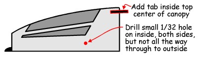 Glue the canopy to the canopy frame that was cut off the canopy pod top, and very carefully fill the seams if necessary, trying to do it without damaging the canopy. The supports for holding the canopy in the open position are a small plastic tab on the top inside center of the canopy and two hydraulic pistons attached to the inside on the sides of the canopy. Now, before painting, is the time to add the tab. The small holes on the insides of the canopy should be drilled, but NOT ALL THE WAY THROUGH. Drill them from the inside, but only half way through the wall - just enough to glue the strut ends into.
The first coat of paint on the canopy frames will be visible from the inside with the canopy open, so the OUTSIDE of the canopy and frames will first be painted with the interior color - I used flat black. Mask off the clear canopy parts on the outside, AND the inside of the canopy so it doesn't get overspray inside. Paint the outside of the canopy and frames flat black, and when dry, paint the light grey exterior color over it. When done, you'll see the flat black from the inside when the canopy is in the open position. I wanted a tinted canopy, so I added a tiny bit of black to some Future® floor polish, sprayed the inside of the canopy assembly, and Voila! A tinted canopy! The rest of the interior of the canopy was then hand-painted flat black. 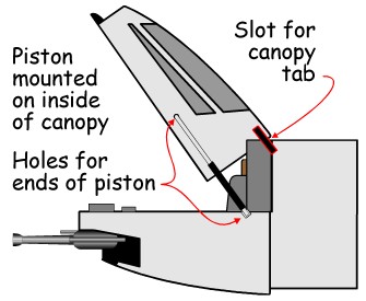 For an open canopy, cut a slot for the tab on the canopy in the sheet plastic between the bulkhead and the top of the pod, and drill two holes in the bulkhead for the bottoms of the hydraulic pistons.
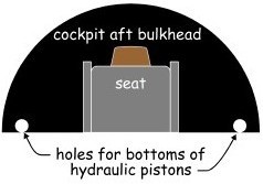
|
The hydraulic pistons were made from chromed sewing pins and insulation off a piece of small wire. I cut the head and point off a pin, filed the ends flat, bent one end over at 90 degrees, then trimmed the bent end short and ground it flat. Some sewing pins are brittle, so it may take several tries to get a clean 90 degree bend without breaking the pin. Slide a piece of black electrical wire insulation over the pin so that the bottom end of the pin sticks out just enough to fit in the hole in the bulkhead.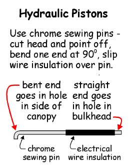
|
|
|
The Wing Landing Gear Bay Do NOT start the main wing assembly by glueing the two wing halves together! The first step is to cut a landing gear bay for the wing landing gear. After extensive research, and not a little guess-work, I decided on a size and location for the landing gear bay. After scribing the location with a straight-edge, I carefully cut a rectangular hole in the bottom wing half for the landing gear bay, cleaned it up with a file, then glued a piece of sheet plastic to the inside of the wing to close it off. NOW the two wing halves can be glued together, but DO NOT trap the cockpit pod or weapons pod between them when gluing them together. Those assemblies will be added later after detailing and painting. 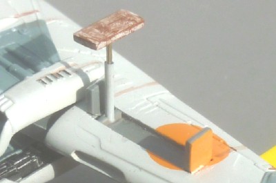 The Wing Landing Gear
The landing gear leg hydraulic strut was made from a piece of chrome music wire slipped into a piece of plastic tubing representing the hydraulic cylinder. A round piece of plastic rod represented the hinge in the landing gear bay. The landing gear pad was a piece of sheet plastic with two pieces of curved sheet plastic glued to the top to represent the strut hinge point. The strut and pad assembly were glued together, painted, weathered, and set until the model was finished. The landing gear pad was sized to double as part of the landing gear door combination - laying the two landing gear doors and the landing pad down end-to-end produced a door length combination equal to the length of the landing gear bay. The landing gear and landing gear doors were glued in place AFTER the entire model was finished so that it could be shimmed to sit level on the gear. just for fun, I put together a sequence of how this particular landing gear retraction system might work . . . First, the landing pad rotates 90 degrees for retraction (top view) . . . |
Landing pad in landing position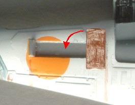 |
Landing pad rotated for retraction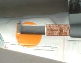 |
Landing pad in landing position (rear view)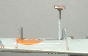 |
Landing pad rotated for retraction (rear view)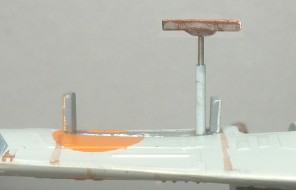 |
. . . then the hydraulic strut retracts . . .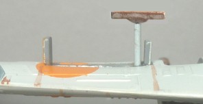
|
. . . and folds into the wing . . .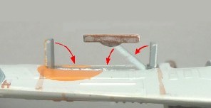
|
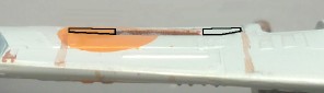 . . . resulting in a smooth surface on the bottom of the wing. The two black outlines would be the two small landing gear doors, and the rusty center part is the bottom of the landing pad. |
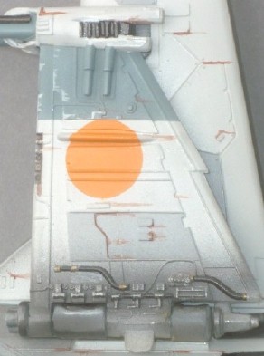
The Main Wing Weapons Pod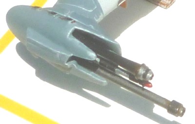 The main weapons pod is located at the very end of the main wing. In the kit, the weapons assembly is glued in place before the wing halves are assembled. I wanted to be able to detail both the wing and the weapons assembly, so I cut the tab off the weapons bulkhead, and spent a little time scraping and cutting the pod and the weapons bulkhead so that the bulkhead would slip into the pod AFTER the wing was assembled. This allowed me to detail the weapons separately from the wing.
One of the first issues with the weapons assembly was cleaning the flash off the weapons. The mold line on the weapons was quite prominant. I was able to clean up the mold line on the two smaller weapons without making them look too bad, but the main weapon wasn't salvageable, so I cut it off, and drilled a hole in the bulkhead where it had been. The two smaller weapons were detail painted, and a new main weapon was made from brass tubing of the correct length. A small piece of brass tubing just large enough to slip over the end of the main piece of tubing was C/A'd in place for a quite realistic effect, and the tubing assembly was painted gun-metal silver, weathered, and glued into the hole drilled for it in the weapons bulkhead. After the wing had been painted and weathered, the weapons bulkhead was slipped into it's pod and glued in place. 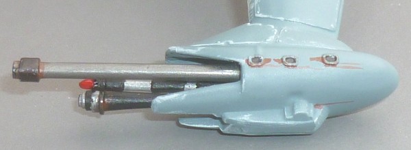 The Main Wing - Cutting It In Half ! The two main wing halves were glued together after making a landing gear bay. Now they get cut in half. This will facilitate detailing the engine pod without the wing in the way. The four locating pins on the center section, two on the top, and two on the bottom, are also cut off at this time. The diagram below shows two of the four pins to be removed and the cut to be made. 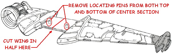 |
|
The Cross-Wing Assembly (the folding wings) The cross-wing assembly is one of only two assemblies not modified from the kit parts. Glue the cross-wing assembly parts together, paint them, detail them, weather them, and set them aside. 
|
|
 Don't forget to detail the "bottom" of the cross-wing weapons pods! |
 The Engine Pod
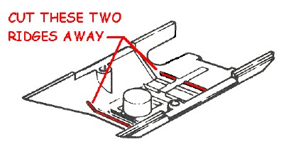
The thruster assembly bulkhead and the engine intake vane bulkhead both fit between ridges inside the engine pod halves. I wanted to be able to detail all these parts separately before assembly, so I cut the forward retention ridge for the engine vane assembly off, and the aft retention ridge for the thruster assembly off. With these two ridges removed, the thruster and vane assemblies can be glued into the engine pod after it is assembled by sliding them into their respective ends. 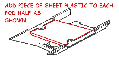 Cutting the wing in half at the center section will make assembling and detailing the engine pod easier, but it makes aligning the wing more difficult when the time comes to glue it in place. To fix this, a piece of sheet plastic was glued across each of the pod halves, making a wing tab slot the width of the pod, and making the wing fit both positive and perfectly aligned.
After completing these two modifications to the engine pod halves, the two halves can be glued together and the seams filled and sanded, and the pod painted, detailed, and weathered. 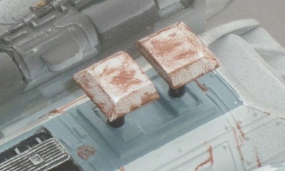 The Main Landing Gear
The main landing gear on the engine pod are relatively straight-forward. I opted to use two main gear. A small piece of sheet plastic was added at each end of the inside of the recess on the bottom of the engine pod. When they were dry, each was drilled for a landing gear strut. Each landing gear strut was made from a piece of plastic rod over which a short piece of plastic tubing was slipped to represent the hydraulic cylinder. The strut was wrapped with Bare Metal foil to give it the look of a polished strut, and the tubing/hydraulic cylinder was painted black. 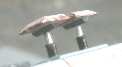 The two short landing pads were made from sheet plastic. A half-round piece of plastic rod was glued to each one, a hole drilled in the center to accept the landing strut, and the strut was glued into the hole in the landing pad. The two main gear leg assemblies were painted, weathered, and set aside. The main gear will be added after the model is finished, so it can be shimmed to sit level.
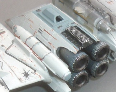 Engine Pod Assembly
Paint the engine intake vanes. When they are dry, you can slide them into the front of the engine pod and glue them in place. In a like manner, the engine exhaust bulkhead is painted, slipped into the rear of the engine pod, and glued in place. Each of the four engine exhausts can now be painted, detailed, weathered, and glued to the engine bulkhead inside the aft of the engine pod. |
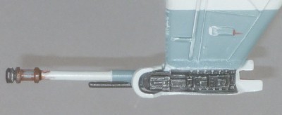
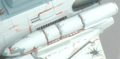 The ?Missile? Pods
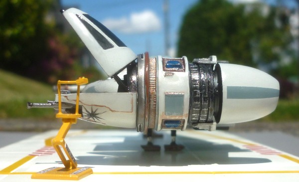
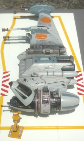
This assembly is the only other part of the model besides the folding cross wings that was not modified. I'm not completely sure what it is, but they look like missile pods, so that's what I'm calling them. Glue the two halves together, clean up the seams, paint and weather the assembly, and set it aside. Final Assembly Since all the sub-assemblies have already been painted, detailed, and weathered, all that's left is to glue them all together. Start by sliding the folding cross wing assembly into it's slot in the outer main wing and glueing it in place. The ?missile? pod assembly is glued into the slot in the short wing half. With these two assemblies completed, the two wing halves can be slipped into the wing slot in the engine pod and glued into place. The two halves of the cockpit module can be slipped into the cockpit pod ring and glued in place. The front half should slide right in. The back half will require a little more effort to be snapped into place between the upper and lower parts of the pod ring. I found that it required no glue to hold it in place on my model. The last part before the landing gear are installed is the main weapons assembly. Slip it into the main weapons pod, and make sure it is aligned properly with both the horizontal centerline of the wing and cockpit pod, and the fore and aft centerline of the weapons pod, before glueing it in place. I propped mine up in the proper alignment and let it dry overnight. The landing gear assemblies were added last. The main gear were glued in place so that the model sat level fore and aft, and when they were dry, the outer wing gear was adjusted until the model sat level from cockpit pod to weapons pod, glued in place, and the model supported in a level position until the gear was dry. The Model Display Base 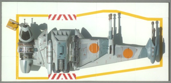 The display base was made from a piece of 1/8 inch thick particle board 8.5 inches by 4 inches with plastic sheeting glued to it. I cut rectangles of plastic sheet and glued them to the top of the board with spray adhesive, then painted the whole affair flat white. When the white was dry, it was masked off and a yellow warning stripe was added around the circumference of the B-Wing fighter. Red warning chevrons in front of the engine intake and behind the exhaust were also added to keep personel away from these two dangerous areas. After painting the edges of the base black, the whole affair was given a coat of Future® floor polish for a gloss "clean room" type affect, and the base was finished.
|
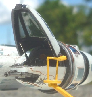
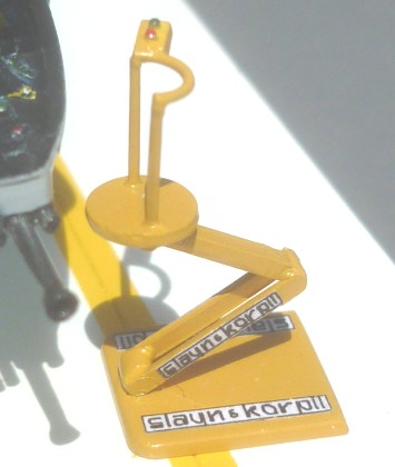 The Crew and Maintenance Lift
I wanted to make a hover crew lift for cockpit access and maintenance work, but anti-gravity technology hasn't filtered down to the modeling community yet, so I had to settle for making a hydraulic lift. You'll just have to use your imagination to see it scooting around the hanger sans wheels. In the spirit of corporate vertical integration, "Slayn & Korpil", the manufacturers of the B-Wing Heavy Assault B-51 Starfighter are thought to have provided the crew lift with the B-Wing, as it has the "Slayn & Korpil" logos plastered all over it (no, it didn't come in the kit - I scratch-built it). Pretty cool, huh? It's little additions like this that make a build fun. 
|
More Pictures !  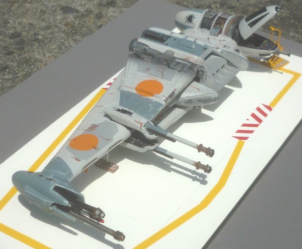 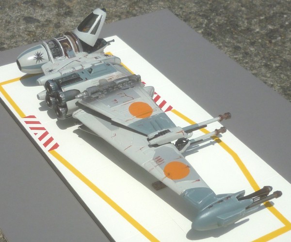 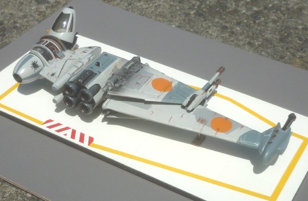 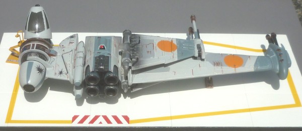 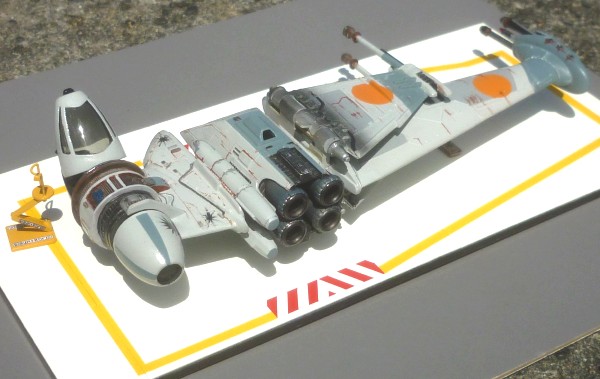 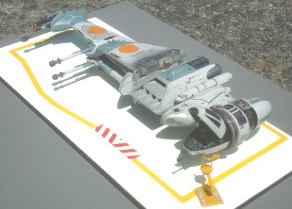 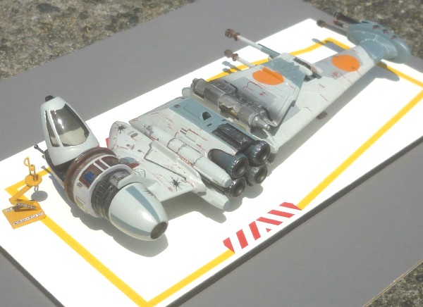 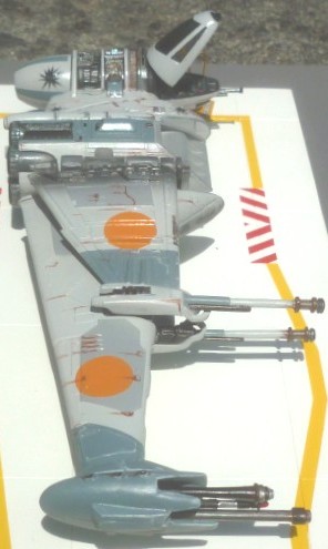
 |
|
 |
| And still MORE pictures . . . |
| Back to the Plastic Scale Modeling page |
|